|
From
SPLASH
Modeling
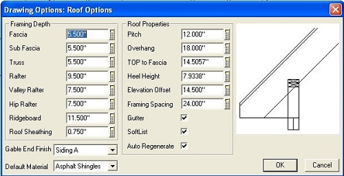
2. Calculating heel height (Download my uploaded document from Byard Misc) use table for 2x6 plate with 2x10 rafter = 7.934"
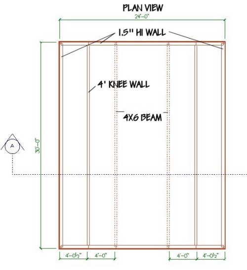
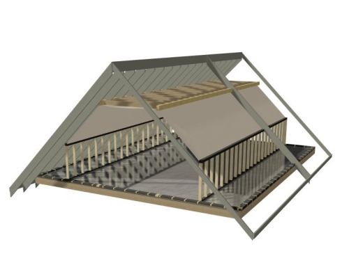
3. Set up Floor jsts paremeters Enter 9.5" for jsts .625" for Sub floor STEP ONE Note my walls have outermost bearing to edge of stud Draw a building 2x6 wall w/siding with dimensions 24' x 30' Edit this wall to 1.5" high You should place a reference point in any one corner Remember to use the same in all floor plans
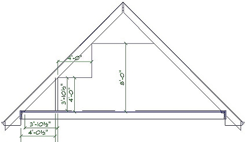
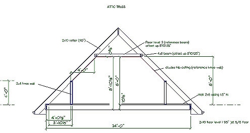
Go to Floor system and add your floor (Level one) Place rim joist and subfloor only Save Drawing as ATTIC TRUSS STEP 2 Place your roof and edit each end to be a Gable Next go to roof framing and select Auto stick frame (Click inside roof poly) STEP 3 Return to drawing mode and place a Section line and Generate a Section and Save it This drawing will help you with offsets and will help you reference the knee walls and beams we will place With the saved section you can use simple lines to calculate the wall heights and offsets with the Dimension, offset, snap and trim tools Remember to set your shape dimension options to edge for extensions I first placed a regular line vertically and dimensioned it so that it was 3' 10.5" from the intersection of the rafter and plate on the inside of the wall When this line is trimmed to the underside of rafter and to the floor it will be 4' high the height of the actual knee wall we will place I also offset a line from the top of sub floor 8' then measured the offset back to the bottom of the floor (8' 10.125")= Beam offset and second level floor offset From this section info we can go back to the ATTIC TRUSS drawing and add the knee wall and our 4x6 beams we will require
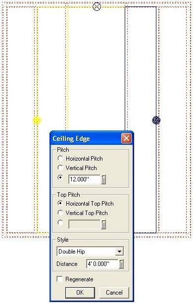
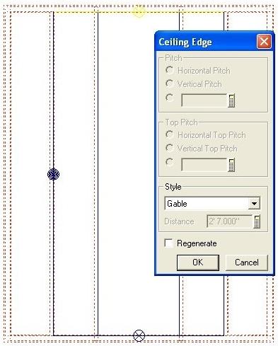
STEP 4 Place 2x4 knee walls and edit to 4' high place Beams 4x6 and edit to 8'10.125" offset up Go to CEILING mode and Place a double hip roof that references the knee walls edit as below
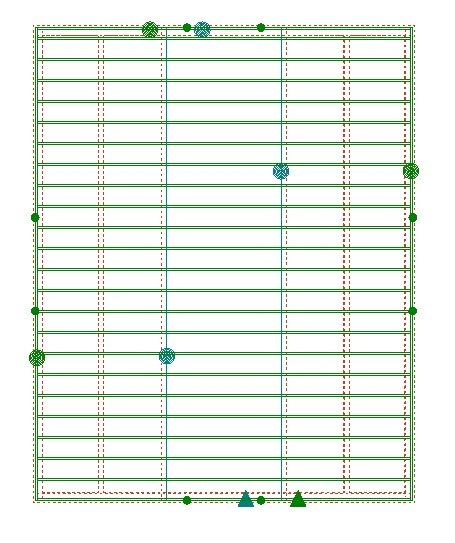
STEP 5 Go to FLOOR mode and place a Floor (JOISTS only) manual trace around inner beams and exterior walls name it level 2 and offset up 8'10.125"
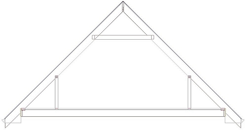
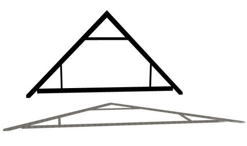
STEP 6 In DRAWING mode generate a new section It should look like below
STEP 7 From the saved Cross section you could trim lines so that they all meet and erase ones that you wont require and then use the FORM POLYGON Command To create a dxf model of an individual truss Give each Polygon a depth and then generate a 3d drawing with the saved section as your assembled floor then export it as dxf r14 open in Crossroads and rotate it 90 degrees on the x axis
© Copyright 2004 by SPLASH http://www.softplansplash.org |