|
From
SPLASH
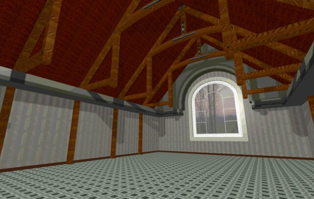
Modeling Another method for creating 3D Models can be the use of generated cross sections as well as saved Elevations. These work well as templates for such things as arches around windows or Timberframes as seen below.
The method is the same as was used for creating the Solarium model using the dxf utility wcvt2pov for rotating the model. In this example the Timberframe was made first then the connectors model second. You need to do this so that you can attach different textures to different parts of the model. If you assemble all the parts at once only one texture will be applied to that part of the model. Open your saved cross section and create your template. Use Solid/Polygon to trace your model outline. Give it a depth and then flip it to make the model vertical. Follow this by creating a 2D symbol (refer to solarium article for specifics)
One important thing to remember when creating your 2D symbol is the total height of the model. You can dimension your cross section or simply use Ctrl from - to in order to get this measurement from your sections. Record this measurement since you will need it when stacking and building your 3D symbols. SoftPlan enters the word "default " for the height when you go to edit the symbol so if you are stacking different models on top of each other you need to know the height of each progressive model . In the graphic you will notice a cube in the bottom left hand corner for a base and a connector plate at the top. The connector model was given a height of 19'-5". It was created this way so it aligned with the timberframe model which also has a height of 19'-5". Offsets and total height are important to get the final model to align correctly. © Copyright 2004 by SPLASH http://www.softplansplash.org |