A Method for Creating a Cape Cod House with Dormers
By Dean M. Eckman, D.M.E. Drafting
Nov 7, 2000
SoftPlan is an excellent tool for designing cape cod style homes, with a little understanding as to how things work. Using the methods outlined below, SoftPlan will help you figure out the height of the knee wall at a given pitch, or the location of the knee wall if the pitch and knee wall height is predetermined. The method used for any task in Softplan will be determined by the final output you require. In other words, if you are only interested in 2D working drawings, you would use one method, if a material list is required, another method might be better, if accurate 3D rendering is your goal, still another method may be employed. This tutorial is designed with 2D working drawings and 3D rendering in mind. Because there are so many variables, it is necessary to make some assumptions before we begin. These assumptions are: The attic room will be built over a 24' x 28' garage, and The room is to be as large as possible while maintaining a 5'0 high knee wall, and The roof pitch will be 10/12 using 2x10 rafters. To begin, create a new folder and start a new drawing called "First floor plan". Draw a 24' x 28' building using the 2x4 siding wall (for the purpose of this tutorial, I will not be creating a foundation plan and will ignore the first floor wall offsets). Go to file/drawing options/material dimensions/roof options and set the rafter depth to 9.5", the pitch to 10, the overhang to 10.5 and the TOP to fascia to 4.25. Save the drawing and do a ;save as to create the second floor plan. In the second floor plan, using the wall height command, change the wall offsets to 10.25 (9.5 floor joists and .75 subfloor). The profile should look like this:
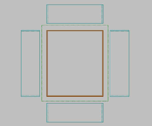 |
Move the rear wall down 6' and the front wall up 6' and edit the rear and front walls to 5' height.Remember to uncheck "Attach" Click file/drawing options/define wall/edit. Highlight the 2x4 siding wall and click save as and name the new wall 2x4 siding non bearing. Hit [Enter] and highlight the new wall. Remove all bearing references. Click OK, which will return you to the second floor plan. Edit the end walls to the new wall type and adjust them passed the front and rear walls and add break lines. Your drawing should look like this:
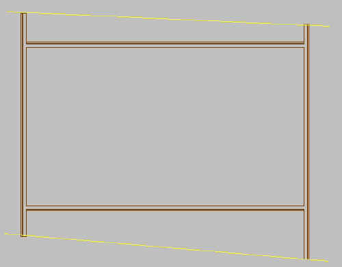 |
Go to roof mode and click multi-floor roof and bring in the first floor. Using trace roof, add a roof and edit the left and right ends to gable. Auto stick-frame the roof and go back to the first floor plan. Go to ceiling mode and add 2x10 ceiling joists front to back. Click build/assemble floors and add the first floor and then the second floor. Add a section line vertically through the building and generate a cross section, be sure to check background. Save the section and exit SoftView and open the section drawing. Your section should look like this:
 |
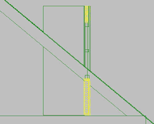
Zoom in to where the right wall intersects with the rafter:
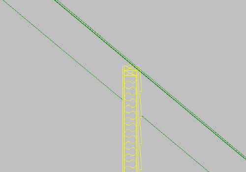 |
Move the top plate until it intersects properly with the rafter and note of the distance you moved the plate or dimension the distance. In this example, the wall needs to be moved 1'0.5.
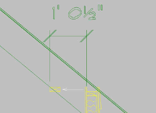 |
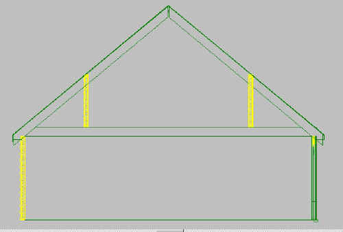
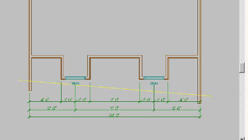
Go back to the second floor plan and move the rear wall down 1'0.5 and the front wall up 1'0.5. Regenerate the section to check the results. The new section shows that, using the predetermined criteria; the room width would be 13'2.
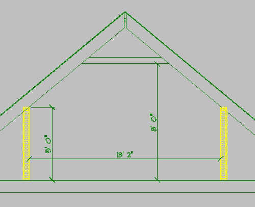 |
Let's put some dormers on it. Go back to the second floor plan and add two windows to the front wall and edit them to the equivalent of an Andersen 28310. Add extensions and position the first window 6’6 from the right wall to the centerline, and separate them 11'0 from centerline to centerline. Using erase/block cut" cut the wall on both sides of the windows. Your drawing should look like this:
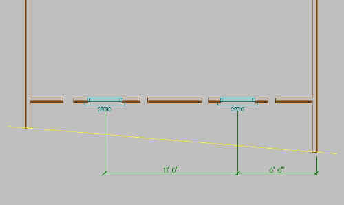 |
Edit the wall sections with the windows back to 8' height and move them down 3'0. Add 2x4 siding walls to the sides. Put extensions on the walls and edit the dimensions to 2'0 each to create 4'0 wide dormers with the windows centered. Use fillet to join the walls. Your drawing should look like this:
 |
Go to the first floor plan and, after checking to make sure that the section line goes through one of the dormers, (this can easily be done using overlay) generate another cross section. The cross section reveals that the dormer front wall needs to be moved out.
 |
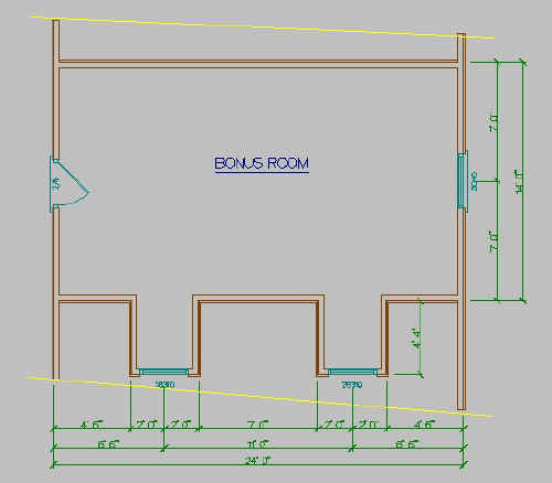
Return to the second floor plan (drawing mode) and move the dormer walls out 1'4. Add an end wall window, notes and other detail to complete the second floor working drawing, which may look something like this:
 |
Return to the second floor roof mode and click "multi floor roof and bring in the first floor plan. Add a roof to each dormer and edit the front edge to gable. The dormer roofs will intersect properly with the first floor roof because the first floor roof was actually created on the second floor plan. We're now only a few steps away from creating a 3D rendering of the structure. Make a copy of the second floor and call it second floor for render. In the second floor for render (drawing mode), click on options/visible items and put a check in roof outline. Adjust the right wall to be even with the roof outline on the top end and the bottom end. Edit the wall and change the offset to zero and click fit top of wall to roof. Go to roof mode and make sure that there is not a check in gable end provided by roof. Edit the window offset to approximately 6'8 up. Go to profile mode and adjust the dormer side walls up to intersect with the roof. The profile will look something like this:
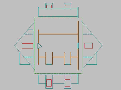 |
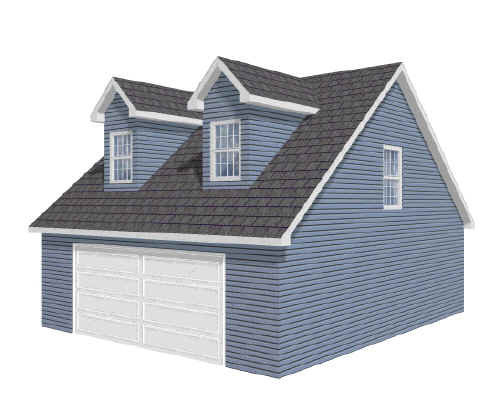
Generate the 3D view.
Congratulations, you now have a Cape Cod house, complete with a rendering! Now it’s time to add a background, driveway, grass, trees, shrubs and shadows…then again, this will wait for the next article.
© Copyright 2004 by
SPLASH http://www.softplansplash.org